
In energy storage systems, busbars may seem ordinary, but they serve as the “electrical hub,” critical to performance, safety, and longevity. From careful material selection to precise insulation design, strict technical standards, and meticulous surface treatment, every aspect impacts the overall system. Here, we analyze energy storage busbars from the perspectives of structural design, materials and component selection, and process engineering experts.
Busbar Materials: Balancing Performance and Selection
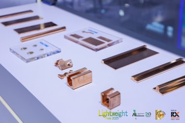
· Advantages and Types of Copper
Copper stands out in busbar selection for its exceptional conductivity. For example, T2 electrolytic copper has conductivity ≥58 MS/m, minimizing resistance losses. In a 1 MWh system at 1,000 V and 1,000 A continuous current, following a current density ≤3 A/mm², at least 120 mm² cross-section busbars are required. T2 copper ensures heat generation remains controlled under high currents.
· Other grades include T1 and T3 copper. T1 has higher purity and fewer impurities, offering better conductivity at higher cost, suitable for high-end projects. T3 contains more impurities, with slightly lower conductivity but lower cost, used in cost-sensitive applications.
· Special Environmental Considerations
For high-temperature, high-humidity, or corrosive environments, alloyed copper (e.g., with tin or nickel) improves corrosion and oxidation resistance. Coastal energy storage stations often use nickel-containing alloys to resist salt corrosion, while high-temperature industrial heat storage systems require copper with thermal stability to maintain performance.
Insulation Protection: Safeguarding Power Transmission
· Insulation Materials and Characteristics
PVC is widely used for cost-effective, processable insulation, forming uniform layers via dip-coating, with dielectric strength of 20–28 kV/mm, supporting ≥3,500 V AC/DC. Epoxy offers superior insulation and mechanical strength, with resistivity >10¹⁵ Ω·cm and breakdown voltage 50–80 kV/mm, ideal for high-voltage systems. Silicone rubber maintains elasticity and insulation from –50 °C to 200 °C, suitable for fluctuating temperature environments.
· Insulation Processes and Performance
Dip-coating involves preheating busbars, immersing them in gel-like insulation material, and curing to ensure adhesion. For PVC, peel strength ≥4 N/cm is achievable. Insulation tape wrapping is also used, such as polyimide tape for high-temperature resistance and butyl rubber tape for waterproofing in humid conditions.
· Fire and Explosion Protection
Fire-resistant self-adhesive tapes, like Andy Fireproof Tape, form a ceramic layer under flame, maintaining insulation. In battery packs, multi-layer application prevents thermal runaway propagation, extending safety response times by 300%.
Technical Standards: Ensuring Reliable Performance
· Current Carrying Capacity
Busbars must handle high currents. Calculations consider material properties, cross-section, ambient temperature, and cooling. According to GB/T 24276–2017, internal cabinet temperature is typically 20 °C higher than ambient. For a 100×10 mm² flat busbar, rated current is 2,174 A; vertical placement improves cooling to 2,265 A. Verification via temperature sensors under load ensures compliance. Large-capacity cells, like Olympus’s 3,777 Ah cells, demand precise calculation and validation.
· Temperature Rise and Heat Dissipation
Excessive temperature increases resistance and degrades insulation. Vertical busbar placement improves convection, tin or silver plating reduces contact resistance, and thermal pads enhance heat transfer. Large systems may employ forced air or liquid cooling to maintain safe operating temperatures.
· Connection Reliability and Mechanical Strength
Connections, via welding or bolting, impact system stability. Welding ensures low-resistance, robust joints but complicates maintenance; bolting allows easier service but requires proper torque. Busbars must withstand handling, vibration, and shocks; in harsh environments, protective casings may be used.
Surface Treatment: Enhancing Performance and Longevity
· Tin Plating
Tin improves oxidation resistance and solderability. Thickness ranges 5–15 μm depending on environment; 5–8 μm suffices for most applications, 10–15 μm for outdoor stations.
· Nickel Plating
Nickel enhances corrosion resistance, wear resistance, and high-temperature stability. Thickness ranges 3–10 μm.
· Anti-Oxidation Coatings
Organic polymer coatings form protective layers, are cost-effective, and can remain intact under bending or deformation. Suitable for small-scale energy storage projects with cost constraints.
· Comprehensive Surface Effects
Plating slightly increases surface resistance, generally negligible. Anti-oxidation coating thickness and uniformity must be controlled. Nickel offers better corrosion resistance; tin works well in normal conditions; coatings vary by material but protect adequately in moderate corrosion. Nickel enhances hardness; coatings improve flexibility, reducing surface damage.
Although small, energy storage busbars embody significant technical value. Material choice, insulation, technical standards, and surface treatment interconnect to determine system performance and safety. Continuous optimization ensures high-efficiency, stable operation of modern energy storage systems.
Source:Tencent